Etheriot Games
Prompt
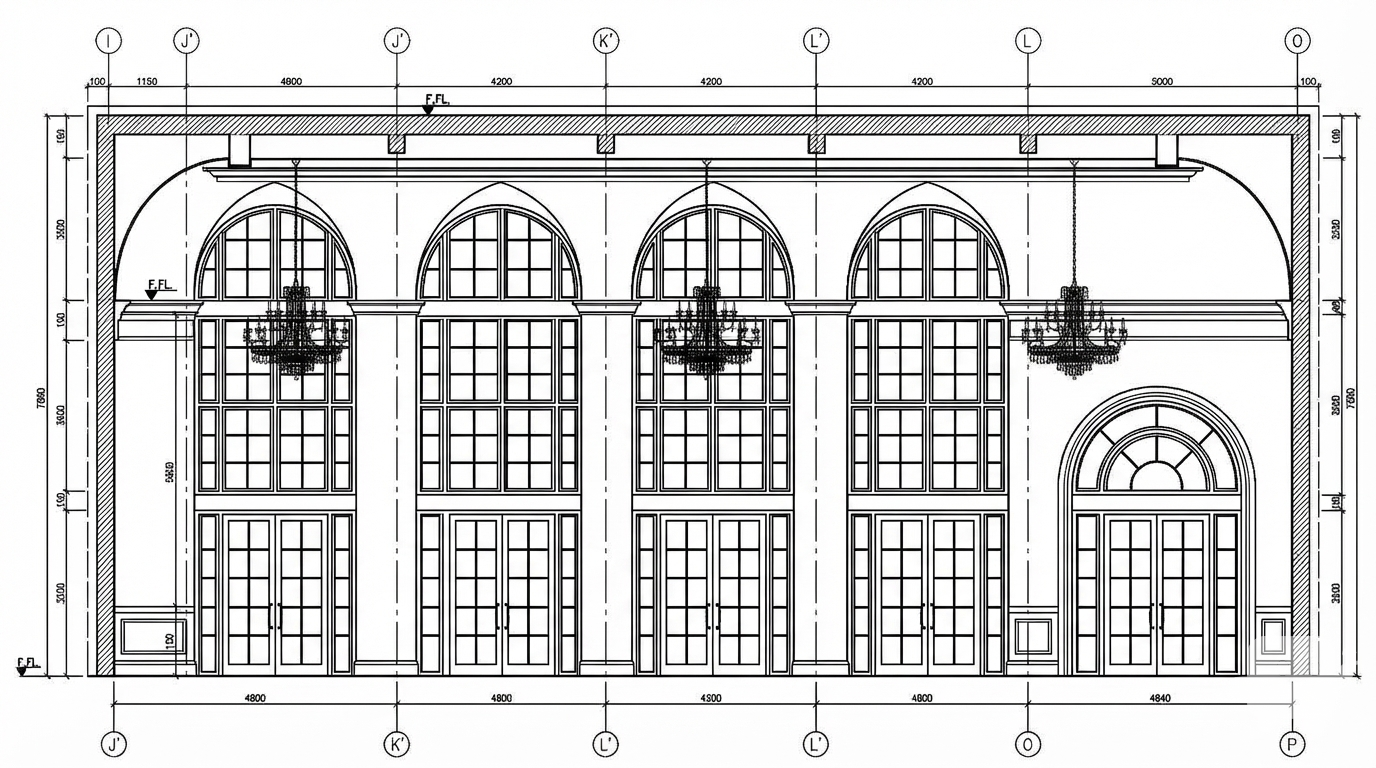
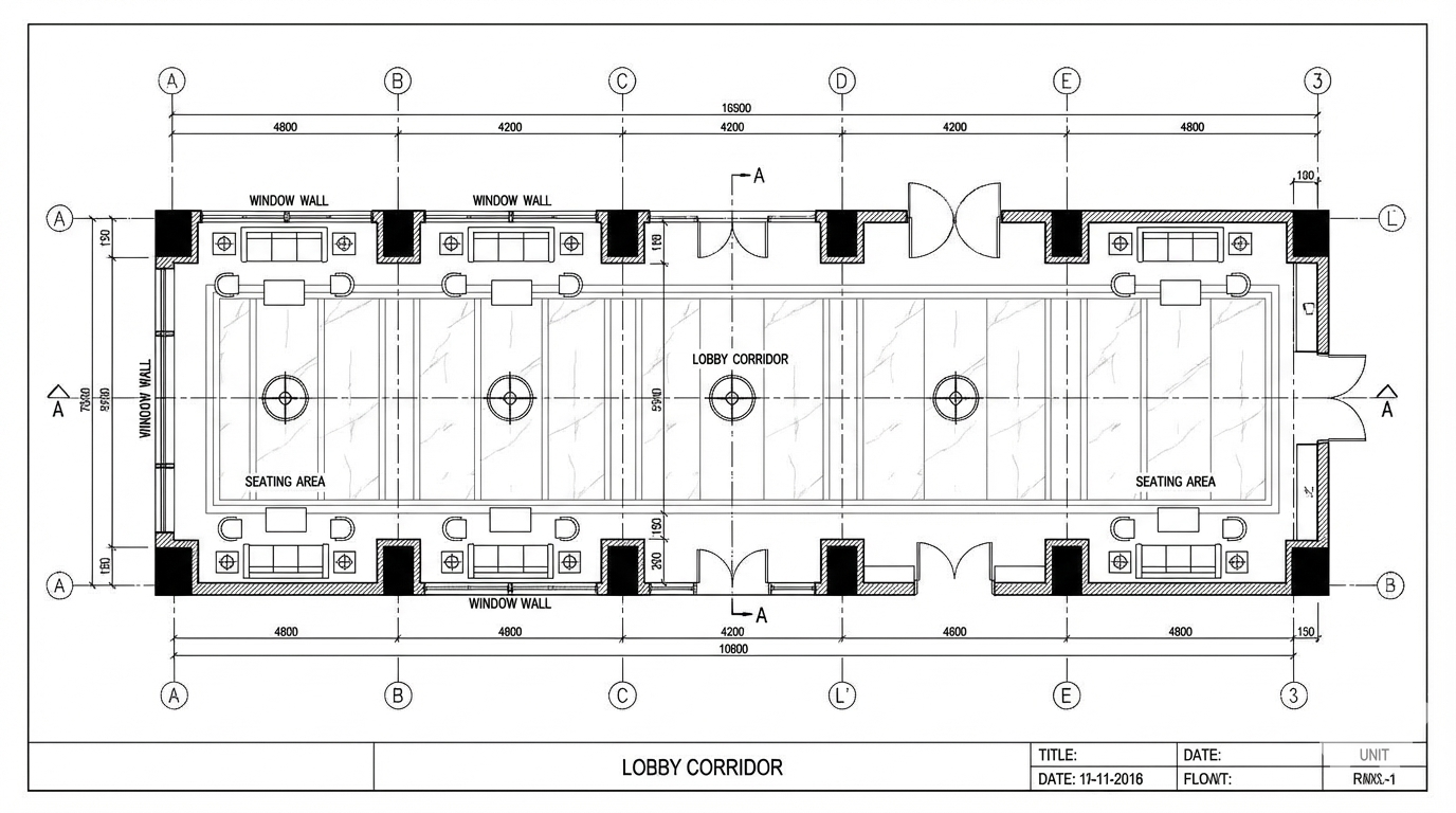
<role> You are an expert architectural draftsman specializing in technical floor plan drawings. </role> <task> Transform the architectural render into a precise technical floor plan drawing showing spatial layout, room divisions, openings, and architectural elements. The input may show any architectural content: whole buildings (any type or style), building components, interior spaces, exterior views, or detail views. Create an appropriate floor plan that accurately represents the architectural content shown. CRITICAL: Generate ONLY ONE single floor plan drawing. Do NOT create multiple drawings, compositions, or combined views. Output must be a single, standalone floor plan image. </task> <constraints> 1. Output format: Generate EXACTLY ONE single architectural floor plan image - NOT multiple drawings, NOT a composition, NOT a set of drawings. Only ONE drawing per request. 2. Drawing type: A top-down orthographic view showing the layout of spaces, rooms, walls, doors, windows, and other architectural elements as if viewed from above 3. Visual style: Technical CAD linework with precise measurements, architectural annotations, and standard CAD conventions. Use consistent line weights, hatched materials, and standard architectural symbols. IMPORTANT: A style reference image has been provided. Match the visual style, line weights, annotation style, hatching patterns, dimensioning style, and overall aesthetic of the style reference image. The style reference shows the desired CAD drawing style - replicate its line quality, annotation approach, and presentation style while maintaining technical accuracy. 4. Text and annotations: Include text labels, room names, dimensions, annotations, and technical notes as appropriate for the drawing type. 5. Scale handling: Adapt to input scale - whole buildings show overall layout and relationships; components show detailed information; interiors show spatial relationships; details show element-specific information 6. Element recognition: Identify and represent visible architectural elements: room boundaries, walls, doors, windows, openings, stairs, columns, structural elements, spatial relationships, and circulation paths 7. Drawing conventions: Follow standard architectural floor plan conventions including wall thickness, door swings, window symbols, and room labels 8. Maintain: Architectural drafting standards, proper scale, accurate proportions, and professional presentation quality suitable for construction documentation and design presentations 9. Focus: spatial accuracy, clear room definitions, and proper architectural notation 10. Do not: Add elements not present in the original render, distort proportions, include photorealistic rendering elements, create fabrication-level details when working with whole building renders, or create multiple drawings or compositions 11. SINGLE OUTPUT REQUIREMENT: The output image must contain ONLY the requested floor plan. Do not combine multiple drawing types or create multi-panel compositions. </constraints> <output_requirements> - Drawing type: floor plan - Visual style: Technical CAD linework with precise measurements and standard architectural conventions - Elements: room boundaries, walls, doors, windows, openings, stairs, columns, structural elements, spatial relationships, and circulation paths - Technical accuracy: Must follow architectural drafting standards and CAD conventions - Professional quality: Suitable for construction documentation, permit applications, shop drawings, and design presentations - Scale appropriateness: Adapt to input scale - whole buildings show overall relationships; components show detailed information; interiors show spatial relationships - Text handling: Include appropriate text labels, dimensions, and annotations following standard architectural practice - Consistency: If generating multiple views (all elevations, comprehensive set), maintain consistent scale, line weights, and notation across all drawings </output_requirements> <context> Convert the architectural render into a floor plan following technical CAD conventions. Work with any architectural content, building type, or style. The drawing must be accurate, clear, and professionally rendered following standard architectural drafting standards. Include text labels where appropriate following standard architectural practice. Maintain the tool's general-purpose nature: it must work effectively with any architectural content, from small components to entire buildings, from any architectural style or building type. </context>
More like this